Difference between revisions of "Gendex Oralix AC"
Reinis.veips (talk | contribs) (Added information on ESP32 triac driver and tube warmup.) (Tag: Visual edit) |
Reinis.veips (talk | contribs) (Added comment on verification of the driver circuit.) (Tag: Visual edit) |
||
| Line 34: | Line 34: | ||
[[File:nats_misc_power_cpc1998.jpg|400 px]] | [[File:nats_misc_power_cpc1998.jpg|400 px]] | ||
| − | === ESP32 triac driver === | + | ===ESP32 triac driver=== |
[[File:Oralix AC65 driver.jpg|thumb]] | [[File:Oralix AC65 driver.jpg|thumb]] | ||
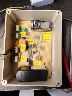
Schematics for driver electronics and firmware for ESP32 can be found [https://github.com/festlv/oralix-ac65s-controller/ here]. The principle of operation is not that different from a light dimmer- optoisolator is used to detect when the mains voltage is at zero, at which point the triac is turned on for pre-determined exposure time. The firmware is written for 50Hz mains frequency- if adapting it for 60Hz tubes, a constant in source needs to be updated for cycle-accurate exposure control. | Schematics for driver electronics and firmware for ESP32 can be found [https://github.com/festlv/oralix-ac65s-controller/ here]. The principle of operation is not that different from a light dimmer- optoisolator is used to detect when the mains voltage is at zero, at which point the triac is turned on for pre-determined exposure time. The firmware is written for 50Hz mains frequency- if adapting it for 60Hz tubes, a constant in source needs to be updated for cycle-accurate exposure control. | ||
| Line 45: | Line 45: | ||
A dental equipment technician recommended to start firing the tube with several short exposure times if it has not been used for some time, which was also confirmed by [http://mpijournal.org/pdf/2018-01/MPI-2018-01-p157.pdf this paper]. | A dental equipment technician recommended to start firing the tube with several short exposure times if it has not been used for some time, which was also confirmed by [http://mpijournal.org/pdf/2018-01/MPI-2018-01-p157.pdf this paper]. | ||
| − | <br /> | + | <br />The driver circuit above was confirmed to be working on a dental X-Ray testing equipment which showed the exact X-Ray radiation waveform. The radiation was produced as half-period pulses (that is: a sinusoidal pulse with 10ms width, followed by 10ms off-time). According to the technician it was the expected waveform. |
| + | |||
| + | The author is not entirely sure about the exact dose down to half-period (e.g. should the tube be turned on at positive or negative zero crossing), but it is good enough for imaging needs. | ||
==Accessories== | ==Accessories== | ||
Latest revision as of 10:52, 4 August 2020
Contents
Description
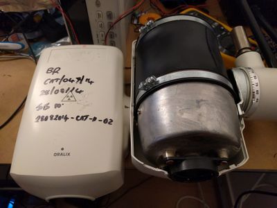
Seems to be simply driven by switching AC 250V. French PDF with brief presentation
- Minimum time is basically 1.5 Period @ 50Hz. Service manual explains that first 120ms (117ms for 60Hz tube) of exposure does not produce significant amount of X-rays and refers to this time as warmup time. Total tube-on time consists of these 120ms warmup time and 30ms to 2.5s of exposure time.
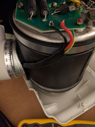
- Only 2 contact and Earth are available.
- (Everything handled internally by multiples coils on transformer ?)
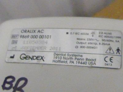
- 65kV @ 7.5mA (sticker says 8.25mA)
- Exposure time: 30ms to 2.5s
- 230V 50/60Hz
- Tubehead is oil filled and shielded.
- Focal point size: 0.7mm
- Duty cycle 1:30 (with a 3s minimum)
- Radiation output: 5 mGy/sec +/-30% at 20 cm from the focus
- Original control unit performs exposure time compensation for varying mains voltage (in +/- 10% range).
Driving
Project in progress:
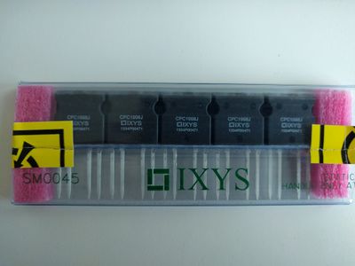
- Certainly will use IXYS CPC1998
ESP32 triac driver
Schematics for driver electronics and firmware for ESP32 can be found here. The principle of operation is not that different from a light dimmer- optoisolator is used to detect when the mains voltage is at zero, at which point the triac is turned on for pre-determined exposure time. The firmware is written for 50Hz mains frequency- if adapting it for 60Hz tubes, a constant in source needs to be updated for cycle-accurate exposure control.
The Arduino in schematics was replaced with ESP32 as that is what I found, which actually works out ok as it provides one additional layer of galvanic isolation and allows remote tube control over telnet. Also, the second optoisolator is redundant- I initially wanted to detect the mains polarity, but the concerns of RCDs being tripped due to opto LED current were greater, so only the "positive" one is used in firmware. I also replaced the L7805 with DC-DC switcher to power ESP32.
The accuracy of exposure time was measured using low-voltage transformer instead of mains input. I also added neon tube for manual mains input polarity detection (not sure it matters but service manual did make this distinction so better safe than sorry) and several LEDs for armed/firing status indication. By default the fire command performs warmup and checks that minimum cooling period is maintained. However there is a fire_nowarmup command that has a resolution of 10ms (good idea when first firing the tube).
Next step of the testing was using a light-bulb as load which was a success (after the remains of resistors in parallel to 47K which were added for testing with a low AC voltage input during debugging was scraped off the board).
A dental equipment technician recommended to start firing the tube with several short exposure times if it has not been used for some time, which was also confirmed by this paper.
The driver circuit above was confirmed to be working on a dental X-Ray testing equipment which showed the exact X-Ray radiation waveform. The radiation was produced as half-period pulses (that is: a sinusoidal pulse with 10ms width, followed by 10ms off-time). According to the technician it was the expected waveform.
The author is not entirely sure about the exact dose down to half-period (e.g. should the tube be turned on at positive or negative zero crossing), but it is good enough for imaging needs.
Accessories
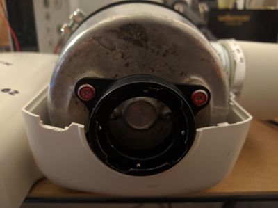
I need a collimator, maybe will be done in steel + lead.
Reinis: my tube is also missing a collimator, so any information on the geometry/construction of original collimator would be welcome.
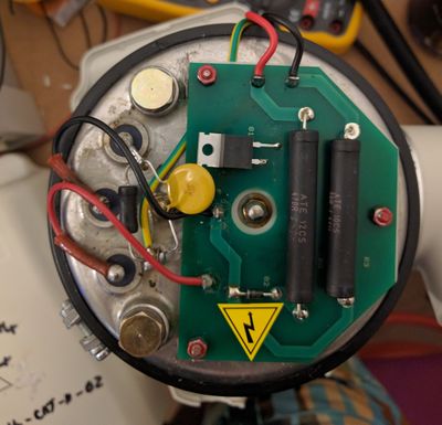
External electronics on tube
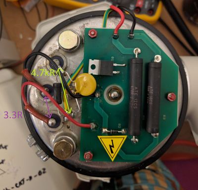
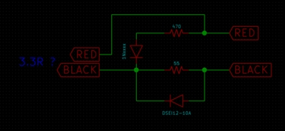
Resistor parallel to MOV is 4.7kΩ, when removed it becomes high impedance. Measure were made with disconnected Red and Black wires.
No contacts have link with the metal casing (ground).
PCB Schematic:
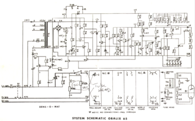
Seems to be confirmed by the schematic of Oralix 65
