Difference between revisions of "Gendex GXS700"
(Tag: Visual edit) |
|||
| (4 intermediate revisions by 2 users not shown) | |||
| Line 1: | Line 1: | ||
| − | [ | + | [[GXS700 FOSS|GXS700 FOSS toolkit]] |
Sold as: | Sold as: | ||
| − | * [http://www.gendex.com/gxs-700 Gendex GXS700] (Gendex (GX) S-700 => GX S-700 => GXS-700) | + | |
| − | * [http://www.dexis.com/sensor Dexis Platinum] | + | *[http://www.gendex.com/gxs-700 Gendex GXS700] (Gendex (GX) S-700 => GX S-700 => GXS-700) |
| − | * "PerfectSize™ Sensor—One Size Fits All" | + | *[http://www.dexis.com/sensor Dexis Platinum] |
| + | *"PerfectSize™ Sensor—One Size Fits All" | ||
My understanding is that Gendex and Dexis are both held by the same company. The sensors seem to actually be made by Fairchild Imaging (now BAE). So I'm not sure what to actually call them. Gendex gave them a real model number (GXS700) so I rolled with that. | My understanding is that Gendex and Dexis are both held by the same company. The sensors seem to actually be made by Fairchild Imaging (now BAE). So I'm not sure what to actually call them. Gendex gave them a real model number (GXS700) so I rolled with that. | ||
| − | + | TODO: add some external device pictures, especially comparing small and large | |
| + | =Overview= | ||
| − | + | Quick facts | |
| + | *Linear pixel size: very roughly 18.2 um | ||
| + | *1850 x 1344 (large) => 1.324 x 0.962" | ||
| + | *14 bit | ||
| − | |||
General theory of operation based on protocol reverse engineering. | General theory of operation based on protocol reverse engineering. | ||
| Line 26: | Line 30: | ||
Internally the major components are: | Internally the major components are: | ||
| − | |||
| − | |||
| − | |||
| − | |||
| − | |||
| + | *FX2 MCU | ||
| + | *EEPROM (for FX2) | ||
| + | *Actel FPGA | ||
| + | *16 bit sensor | ||
| + | *Flash | ||
| − | = Bare sensors = | + | |
| + | =Bare sensors= | ||
Some of these were sold at defcon 22. Look something like this: | Some of these were sold at defcon 22. Look something like this: | ||
| Line 56: | Line 61: | ||
| − | = PCB = | + | =PCB= |
[[File:mcmaster_gendex_gxs700_pcb_top.jpg|250 px]] | [[File:mcmaster_gendex_gxs700_pcb_top.jpg|250 px]] | ||
| Line 63: | Line 68: | ||
| − | == Flash == | + | ==Flash== |
"128 Megabit CMOS 3.0 Volt Flash Memory with 104-MHz SPI (Serial Peripheral Interface) Bus" | "128 Megabit CMOS 3.0 Volt Flash Memory with 104-MHz SPI (Serial Peripheral Interface) Bus" | ||
| Line 74: | Line 79: | ||
| − | == FPGA == | + | ==FPGA== |
Sticker: | Sticker: | ||
| Line 87: | Line 92: | ||
ZA637115 | ZA637115 | ||
| − | == FX2 USB controller == | + | ==FX2 USB controller== |
"CY7C68 Series 16 kb RAM EZ-USB FX2LP USB Microcontroller" | "CY7C68 Series 16 kb RAM EZ-USB FX2LP USB Microcontroller" | ||
| Line 97: | Line 102: | ||
| − | == MT unknown == | + | ==MT unknown== |
9WA47 | 9WA47 | ||
| Line 107: | Line 112: | ||
| − | == 274 == | + | ==274== |
274 | 274 | ||
| Line 114: | Line 119: | ||
| − | == USB connector == | + | ==USB connector== |
[[File:gendex_gxs700_usb_flex.jpg|300 px]] | [[File:gendex_gxs700_usb_flex.jpg|300 px]] | ||
| Line 120: | Line 125: | ||
5 pin ribbon cable | 5 pin ribbon cable | ||
| − | * 1: +5V | + | *1: +5V |
| − | * 2: GND | + | *2: GND |
| − | * 3: D+ | + | *3: D+ |
| − | * 4: D- | + | *4: D- |
| − | * 5: N/C? | + | *5: N/C? |
| − | * Goes to unpopulated capacitor or something | + | *Goes to unpopulated capacitor or something |
| − | = Die = | + | =Die= |
No maker's mark observed on die. There are some foundry marks but that probably won't be very helpful even if the foundry is identified | No maker's mark observed on die. There are some foundry marks but that probably won't be very helpful even if the foundry is identified | ||
| − | = CNC machine = | + | =CNC machine= |
DIY XY scanner | DIY XY scanner | ||
| Line 139: | Line 144: | ||
| − | = Misc = | + | =Misc= |
From anonymous source: | From anonymous source: | ||
| − | |||
| − | |||
| − | |||
| − | |||
| − | |||
| − | |||
| − | |||
| − | |||
| − | |||
| + | *"I wanted to know how to read a calibration file, and he gave me some advice. I noticed in your python script, your resolution values were larger then what is outputted in the actual x-ray files.. so I used those proportions on a dexis, and finally got the resolution, and removed 4 bytes and enabled endian in ImageJ, and I was finally able to see the calibration file. " | ||
| + | *"Apparently Dexis or Schein won't allow the creation of a calibration file onsite" | ||
| + | *Schein? | ||
| + | *"Dexis had a lot of older sensors calibration files on a server, and it crashed..." | ||
| + | *"There are 3 files in a calibration files. 2 are 4MB size. Those are the dark and flats. The third file is around 276kb or so, and.. as far as I can tell.. this file helps the dexis or gendex gx-picture software to know which sensor it is dealing with. I am told that file can be reused, per sensor. It is a dfm file extension if I recall. So it can be reused on a Dexis, but only Dexis. the dfm for a Gendex size 2 should be reused only on gendex size 2 sensors." | ||
| + | *"For a Dexis, use ImageJ to open the flat and dark calibration files. Open it as raw, check mark the endian box, and remove 4 bytes of data option. Input the resolution in the screenshot." | ||
| + | *"For a Gendex calibration file, you will need to use the resolution you used in your python script." | ||
| + | *"Dexis sensors were calibrated with a machine that could do 16 sensors at a time..." | ||
| + | *"They had a bug in the cypress sdk, and that caused the eeprom to go blank in some cases." | ||
| − | = Calibration files = | + | |
| + | =Calibration files= | ||
Note: uvscada can more or less decode these. We have enough information at this point to possibly generate them | Note: uvscada can more or less decode these. We have enough information at this point to possibly generate them | ||
| Line 160: | Line 166: | ||
Sample file names: | Sample file names: | ||
| − | * 2123456789_dark.flf: dark frame (x-ray off w/ force trigger) | + | |
| − | * 2123456789_flat.flf: flat field (x-ray on w/ uniform beam) | + | *2123456789_dark.flf: dark frame (x-ray off w/ force trigger) |
| − | * 2123456789_dfm.dfm :some sort of design for manufacturability improvements? | + | *2123456789_flat.flf: flat field (x-ray on w/ uniform beam) |
| + | *2123456789_dfm.dfm :some sort of design for manufacturability improvements? | ||
These are just little endian encoded raw sensor data.with a 4 byte header. The dark/flat field corrections appear to be applied host side. Its unclear how the DFM file is used. | These are just little endian encoded raw sensor data.with a 4 byte header. The dark/flat field corrections appear to be applied host side. Its unclear how the DFM file is used. | ||
| − | = Dumps = | + | =Dumps= |
[[Gendex GXS700 Dump]] | [[Gendex GXS700 Dump]] | ||
| − | = Pattern generator = | + | =Pattern generator= |
I've discovered 3 test pattern generators in the small sensors, probably exist in the large sensor as well. These might be useful for diagnosing broken sensors | I've discovered 3 test pattern generators in the small sensors, probably exist in the large sensor as well. These might be useful for diagnosing broken sensors | ||
| Line 182: | Line 189: | ||
| − | = Troubleshooting = | + | =Troubleshooting= |
I get a lot of e-mails about broken sensors. If you find out anything about why yours is broken or how you fixed it I'd be interested. | I get a lot of e-mails about broken sensors. If you find out anything about why yours is broken or how you fixed it I'd be interested. | ||
| Line 191: | Line 198: | ||
Following assumes you have uvscada software setup. Please at a minimum send me, if possible: | Following assumes you have uvscada software setup. Please at a minimum send me, if possible: | ||
| − | # Vendor and model of the sensor you have (ex: Dexis Platinum, Gendex size 2, etc) | + | |
| − | # Diagnostic dump output (in dump directory) | + | #Vendor and model of the sensor you have (ex: Dexis Platinum, Gendex size 2, etc) |
| − | # Dark frame (capture.py -f -e) | + | #Diagnostic dump output (in dump directory) |
| − | ## Please send histogram equalized version (-e above) unless otherwise requested | + | #Dark frame (capture.py -f -e) |
| + | ##Please send histogram equalized version (-e above) unless otherwise requested | ||
Procedure might be something like this: | Procedure might be something like this: | ||
| − | # Does lsusb detect sensor? | + | |
| − | ## No: broken cable. Check for fray, etc | + | #Does lsusb detect sensor? |
| − | # Do a diagnostic dump (dump_dev.py). Did it succeed? | + | ##No: broken cable. Check for fray, etc |
| − | ## No, same lsusb ID: FX2 failed to renumerate. Severe error | + | #Do a diagnostic dump (dump_dev.py). Did it succeed? |
| − | ## No, but something else: hard to tell. I haven't worked with many broken sensors | + | ##No, same lsusb ID: FX2 failed to renumerate. Severe error |
| − | # Capture a dark frame (capture.py -f -e), ie force trigger w/o x-rays. Did it complete without error? | + | ##No, but something else: hard to tell. I haven't worked with many broken sensors |
| − | ## No: maybe sensor is broken. Possibly FPGA | + | #Capture a dark frame (capture.py -f -e), ie force trigger w/o x-rays. Did it complete without error? |
| − | # Does the frame look typical? | + | ##No: maybe sensor is broken. Possibly FPGA |
| − | ## No: misc sensors defects. Probably not repairable. But broken bond wires may be | + | #Does the frame look typical? |
| − | # Capture a flat field (capture.py -e), ie using a real x-ray source and no object. Does it work normally? | + | ##No: misc sensors defects. Probably not repairable. But broken bond wires may be |
| − | ## Never triggered: meh | + | #Capture a flat field (capture.py -e), ie using a real x-ray source and no object. Does it work normally? |
| − | # Your sensor is good I guess? | + | ##Never triggered: meh |
| + | #Your sensor is good I guess? | ||
General notes: | General notes: | ||
| − | * Exposed bond wires are very fragile. If you got a bare sensor they are very easy to destroy. This requires relatively specialized equipment (wire bonding machine) to fix | + | |
| + | *Exposed bond wires are very fragile. If you got a bare sensor they are very easy to destroy. This requires relatively specialized equipment (wire bonding machine) to fix | ||
Some issues I've seen: | Some issues I've seen: | ||
| − | |||
| − | |||
| − | |||
| − | |||
| − | |||
| − | |||
| − | |||
| − | |||
| − | |||
| − | |||
| − | |||
| − | |||
| − | == Image: typical good 1 == | + | *Corrupt EEPROM |
| + | *lsusb shows as an FX2 dev kit | ||
| + | *Repair using your backup, or a backup from another sensor | ||
| + | *Triggers immediately without force trigger or x-ray | ||
| + | *A sensor was doing this | ||
| + | *I think I fixed it with an EEPROM restore so possibly messed up some parameter | ||
| + | *Blotches | ||
| + | *Manufacturing defect? | ||
| + | *Broken sensor bond wires | ||
| + | *Only encountered on bare sensors | ||
| + | *Broken USB cable | ||
| + | *Relatively easy to fix, especially if fix does not have to be watertight | ||
| + | |||
| + | ==Image: typical good 1== | ||
[[File:gendex_gxs700_good_line.png|400 px]] | [[File:gendex_gxs700_good_line.png|400 px]] | ||
| Line 233: | Line 244: | ||
Above (equalized): for the most part this works, although it has a bad line down the middle | Above (equalized): for the most part this works, although it has a bad line down the middle | ||
| − | == Image: typical good 2 == | + | ==Image: typical good 2== |
[[File:gendex_gxs700_good2_dark.png|200 px]] | [[File:gendex_gxs700_good2_dark.png|200 px]] | ||
| Line 245: | Line 256: | ||
Above: flat field raw and histogram equalized | Above: flat field raw and histogram equalized | ||
| − | == Image: uniformly noisy field == | + | ==Image: uniformly noisy field== |
[[File:gendex_gxs700_bad_uniform_noise.png|400 px]] | [[File:gendex_gxs700_bad_uniform_noise.png|400 px]] | ||
| Line 270: | Line 281: | ||
[[File:gendex_gxs700_markus_bad_capture_000_e.png|400 px]] | [[File:gendex_gxs700_markus_bad_capture_000_e.png|400 px]] | ||
| + | At least two sensors which exhibited uniformly noisy image output were confirmed to have damaged bond wires, even while they appeared functional otherwise- enclosure not damaged, enumerates over USB, loads FX2 firmware, reads both flash and EEPROM, serial numbers match, capture can be forced and capture does not start when not forced. | ||
| + | |||
| + | Extent of the bond wire damage can be seen in the following pictures: | ||
| + | [[File:Gendex GSX-700 bond wire corrosion 1.jpg|none|thumb]] | ||
| + | [[File:Gendex GXS-700 PCB missing pads.jpg|none|thumb]] | ||
| + | John's comment:<blockquote>Yeah unfortunately I get a lot of e-mails about bad sensors which is a lot of the cheap units you'll find on eBay (say $60 each). Unfortunately once bond wires and/or pads are destroyed general wisdom seems to be to scrap them</blockquote> | ||
| − | == Image: choppy field == | + | ==Image: choppy field== |
[[File:gendex_gxs700_uvscada_type1_bad.png|400 px]] | [[File:gendex_gxs700_uvscada_type1_bad.png|400 px]] | ||
| Line 277: | Line 294: | ||
This was caused by a uvscada bug on type 1 sensors. Using a recent version should fix this | This was caused by a uvscada bug on type 1 sensors. Using a recent version should fix this | ||
| − | == Bad read w/ issue == | + | ==Bad read w/ issue== |
https://twitter.com/FauthNiklas/status/976402053181341697 | https://twitter.com/FauthNiklas/status/976402053181341697 | ||
| Line 284: | Line 301: | ||
| − | = Disassembling = | + | =Disassembling= |
| + | |||
| + | https://twitter.com/johndmcmaster/status/1158276389713276928?s=20 | ||
| + | |||
| + | https://twitter.com/johndmcmaster/status/1158279457280413701?s=20 | ||
The case may be ultrasonically welded together | The case may be ultrasonically welded together | ||
| Line 292: | Line 313: | ||
The sensor appears to be bonded to the PCB with silicone. Acetone slightly weakens it but not enough for bulk removal. Heat gun (400F IIRC) weakened it enough to remove relatively easily. Also tried lighter fluid and mineral spirits but didn't come off. Suggested to try professional silicone remover...will try soon. | The sensor appears to be bonded to the PCB with silicone. Acetone slightly weakens it but not enough for bulk removal. Heat gun (400F IIRC) weakened it enough to remove relatively easily. Also tried lighter fluid and mineral spirits but didn't come off. Suggested to try professional silicone remover...will try soon. | ||
| − | + | MCP maybe came off with acetone ultrasound | |
| − | = References = | + | =References= |
| − | * [https://www.google.com/patents/US8366318?dq=Dental+imaging+Technologies&hl=en&sa=X&ved=0ahUKEwi50bnpxYLNAhXDGJAKHXSVANM4KBDoAQhUMAg Patent] | + | *[https://www.google.com/patents/US8366318?dq=Dental+imaging+Technologies&hl=en&sa=X&ved=0ahUKEwi50bnpxYLNAhXDGJAKHXSVANM4KBDoAQhUMAg Patent] |
Latest revision as of 06:41, 16 September 2020
Sold as:
- Gendex GXS700 (Gendex (GX) S-700 => GX S-700 => GXS-700)
- Dexis Platinum
- "PerfectSize™ Sensor—One Size Fits All"
My understanding is that Gendex and Dexis are both held by the same company. The sensors seem to actually be made by Fairchild Imaging (now BAE). So I'm not sure what to actually call them. Gendex gave them a real model number (GXS700) so I rolled with that.
TODO: add some external device pictures, especially comparing small and large
Contents
Overview
Quick facts
- Linear pixel size: very roughly 18.2 um
- 1850 x 1344 (large) => 1.324 x 0.962"
- 14 bit
General theory of operation based on protocol reverse engineering.
Sensor waits for a certain radiation level (ctr_thresh) before triggering a capture. This presumably is to make a higher quality image by not accumulating noise while the x-ray is coming. It probably also smooths out some boundary conditions as the x-ray head begins to fire. Sensors can also be force triggered by sending a USB command. There is a related trigger parameter (bin_thresh) of unknown function. I have not seen changing it effect the capture in any way.
Once triggered, the sensor integrates for the given number of milliseconds (default 700). Next, a size specific transfer method is used to suck data to the host. Finally, the image is decoded and, optionally, corrected on the host.
Sensors come in two sizes: size 1 (small) and size 2 (large). Think Dexis only makes size 2 sensors.
Sensors come in two brands: Gendex and Dexis. They are packaged differently but otherwise internally identical. There are some software tweaks, notably serial number range.
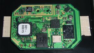
Internally the major components are:
- FX2 MCU
- EEPROM (for FX2)
- Actel FPGA
- 16 bit sensor
- Flash
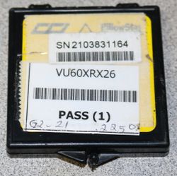
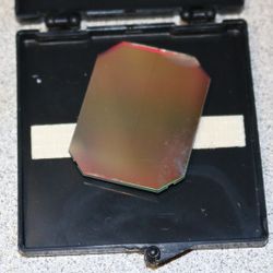
Bare sensors
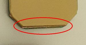
Some of these were sold at defcon 22. Look something like this:
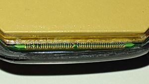
WARNING WARNING WARNING
Bond wires are exposed! Be very very careful handing these! Seen at upper part of sensor above
WARNING WARNING WARNING
JM 2015-11-24: gave away my possibly working bare sensors (3x) and kept 2x definitely broken. Still have 2x encased units
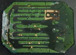
PCB
Flash
"128 Megabit CMOS 3.0 Volt Flash Memory with 104-MHz SPI (Serial Peripheral Interface) Bus"
 SPANSION
 FL128PIF
 12699003 C
 THAILAND
 (C) 06
FPGA
Sticker:
 001-
 00015
Package:
 Actel
 ProASIC3
 A3P250
 QNG132 1140
 ZA637115
FX2 USB controller
"CY7C68 Series 16 kb RAM EZ-USB FX2LP USB Microcontroller"
 CY7C68
 13A4S65
 1131
 642364
MT unknown
 9WA47
 PW6B7

 01Z9

 MT
274
 274
 036
 .VY
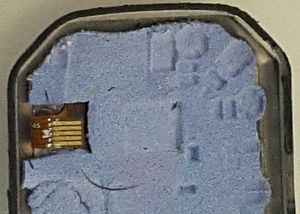
USB connector
5 pin ribbon cable
- 1: +5V
- 2: GND
- 3: D+
- 4: D-
- 5: N/C?
- Goes to unpopulated capacitor or something
Die
No maker's mark observed on die. There are some foundry marks but that probably won't be very helpful even if the foundry is identified
CNC machine
DIY XY scanner
Misc
From anonymous source:
- "I wanted to know how to read a calibration file, and he gave me some advice. I noticed in your python script, your resolution values were larger then what is outputted in the actual x-ray files.. so I used those proportions on a dexis, and finally got the resolution, and removed 4 bytes and enabled endian in ImageJ, and I was finally able to see the calibration file. "
- "Apparently Dexis or Schein won't allow the creation of a calibration file onsite"
- Schein?
- "Dexis had a lot of older sensors calibration files on a server, and it crashed..."
- "There are 3 files in a calibration files. 2 are 4MB size. Those are the dark and flats. The third file is around 276kb or so, and.. as far as I can tell.. this file helps the dexis or gendex gx-picture software to know which sensor it is dealing with. I am told that file can be reused, per sensor. It is a dfm file extension if I recall. So it can be reused on a Dexis, but only Dexis. the dfm for a Gendex size 2 should be reused only on gendex size 2 sensors."
- "For a Dexis, use ImageJ to open the flat and dark calibration files. Open it as raw, check mark the endian box, and remove 4 bytes of data option. Input the resolution in the screenshot."
- "For a Gendex calibration file, you will need to use the resolution you used in your python script."
- "Dexis sensors were calibrated with a machine that could do 16 sensors at a time..."
- "They had a bug in the cypress sdk, and that caused the eeprom to go blank in some cases."
Calibration files
Note: uvscada can more or less decode these. We have enough information at this point to possibly generate them
Some people get these with their sensors to use with the original software (if you have it)
Sample file names:
- 2123456789_dark.flf: dark frame (x-ray off w/ force trigger)
- 2123456789_flat.flf: flat field (x-ray on w/ uniform beam)
- 2123456789_dfm.dfm :some sort of design for manufacturability improvements?
These are just little endian encoded raw sensor data.with a 4 byte header. The dark/flat field corrections appear to be applied host side. Its unclear how the DFM file is used.
Dumps
Pattern generator
I've discovered 3 test pattern generators in the small sensors, probably exist in the large sensor as well. These might be useful for diagnosing broken sensors
Troubleshooting
I get a lot of e-mails about broken sensors. If you find out anything about why yours is broken or how you fixed it I'd be interested.
If you are commercial / have budget, you might consider contacting someone specializing in these sensors (example). But if you are a determined hobbyist on a budget, read on.
Note: a lot of questionable / broken sensors have shown up on eBay. These range from completely broken to working fine. A lot of them seem to have imaging defects that are acceptable for hobbyists but too severe for commercial use. Most of these do not come with calibration files.
Following assumes you have uvscada software setup. Please at a minimum send me, if possible:
- Vendor and model of the sensor you have (ex: Dexis Platinum, Gendex size 2, etc)
- Diagnostic dump output (in dump directory)
- Dark frame (capture.py -f -e)
- Please send histogram equalized version (-e above) unless otherwise requested
Procedure might be something like this:
- Does lsusb detect sensor?
- No: broken cable. Check for fray, etc
- Do a diagnostic dump (dump_dev.py). Did it succeed?
- No, same lsusb ID: FX2 failed to renumerate. Severe error
- No, but something else: hard to tell. I haven't worked with many broken sensors
- Capture a dark frame (capture.py -f -e), ie force trigger w/o x-rays. Did it complete without error?
- No: maybe sensor is broken. Possibly FPGA
- Does the frame look typical?
- No: misc sensors defects. Probably not repairable. But broken bond wires may be
- Capture a flat field (capture.py -e), ie using a real x-ray source and no object. Does it work normally?
- Never triggered: meh
- Your sensor is good I guess?
General notes:
- Exposed bond wires are very fragile. If you got a bare sensor they are very easy to destroy. This requires relatively specialized equipment (wire bonding machine) to fix
Some issues I've seen:
- Corrupt EEPROM
- lsusb shows as an FX2 dev kit
- Repair using your backup, or a backup from another sensor
- Triggers immediately without force trigger or x-ray
- A sensor was doing this
- I think I fixed it with an EEPROM restore so possibly messed up some parameter
- Blotches
- Manufacturing defect?
- Broken sensor bond wires
- Only encountered on bare sensors
- Broken USB cable
- Relatively easy to fix, especially if fix does not have to be watertight
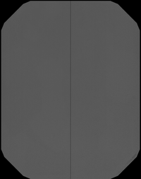
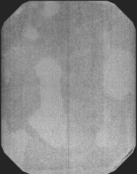
Image: typical good 1
Above (equalized): for the most part this works, although it has a bad line down the middle
Image: typical good 2
Above: dark field raw and histogram equalized
Above: flat field raw and histogram equalized
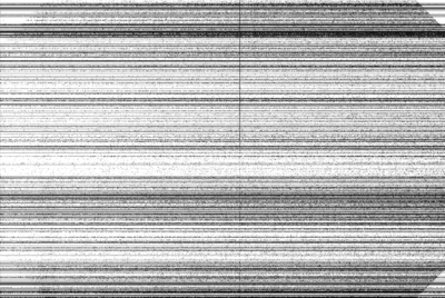
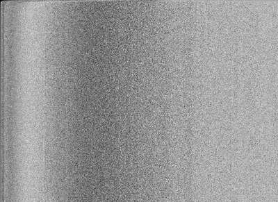
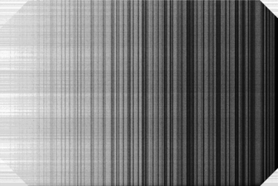
Image: uniformly noisy field
Above: histogram equalized
Unknown issue, reported by a user to me 2017-12-19
Raw data looks like maybe some data and/or address lines are bad
 00000000  00 00 20 00 28 00 10 00  08 00 14 00 04 00 0c 00  |.. .(...........|
 00000010  14 00 08 00 00 00 08 00  08 00 00 00 04 00 04 00  |................|
 00000020  0c 00 10 00 00 00 00 00  0c 00 00 00 00 00 10 00  |................|
 00000030  04 00 00 00 14 00 08 00  00 00 14 00 04 00 00 00  |................|
 00000040  08 00 14 00 00 00 14 00  00 00 00 00 04 00 08 00  |................|
 00000050  08 00 08 00 0c 00 04 00  00 00 10 00 00 00 00 00  |................|
 00000060  00 00 08 00 10 00 04 00  00 00 1c 00 00 00 00 00  |................|
 00000070  00 00 14 00 00 00 00 00  0c 00 00 00 0c 00 0c 00  |................|
 00000080  08 00 00 00 14 00 00 00  00 00 0c 00 00 00 10 00  |................|
 00000090  04 00 00 00 10 00 04 00  00 00 0c 00 0c 00 08 00  |................|
Got something similar from someone else:
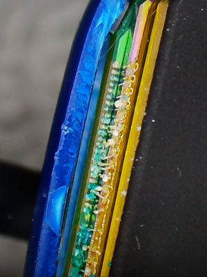
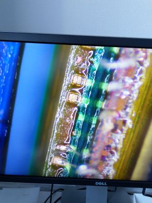
At least two sensors which exhibited uniformly noisy image output were confirmed to have damaged bond wires, even while they appeared functional otherwise- enclosure not damaged, enumerates over USB, loads FX2 firmware, reads both flash and EEPROM, serial numbers match, capture can be forced and capture does not start when not forced.
Extent of the bond wire damage can be seen in the following pictures:
John's comment:
Yeah unfortunately I get a lot of e-mails about bad sensors which is a lot of the cheap units you'll find on eBay (say $60 each). Unfortunately once bond wires and/or pads are destroyed general wisdom seems to be to scrap them
Image: choppy field
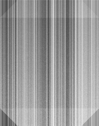
This was caused by a uvscada bug on type 1 sensors. Using a recent version should fix this
Bad read w/ issue
https://twitter.com/FauthNiklas/status/976402053181341697
For some reason the EEPROM S/N wasn't able to be fetched. The sensor image was noisy, turned out to be due to corroded wires between the sensor and PCB. ie sensor disconnected
Disassembling
https://twitter.com/johndmcmaster/status/1158276389713276928?s=20
https://twitter.com/johndmcmaster/status/1158279457280413701?s=20
The case may be ultrasonically welded together
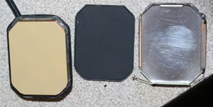
The beige compound comes off in acetone + ultrasound. However, there is a clear protective film over it that significantly slows down the process if it remains on
The sensor appears to be bonded to the PCB with silicone. Acetone slightly weakens it but not enough for bulk removal. Heat gun (400F IIRC) weakened it enough to remove relatively easily. Also tried lighter fluid and mineral spirits but didn't come off. Suggested to try professional silicone remover...will try soon.
MCP maybe came off with acetone ultrasound
