Difference between revisions of "Faxitron"
(→Serial) (Tag: Visual edit) |
|||
| (18 intermediate revisions by the same user not shown) | |||
| Line 1: | Line 1: | ||
| + | TODO 2020-01-05: have significant info to add | ||
| + | |||
| + | |||
Faxitron Bioptics | Faxitron Bioptics | ||
{| class="wikitable" | {| class="wikitable" | ||
| Line 109: | Line 112: | ||
| | | | ||
|21 | |21 | ||
| + | | | ||
| + | | | ||
| + | | | ||
| + | |- | ||
| + | |MultiRad | ||
| + | | | ||
| + | | | ||
| + | | | ||
| + | | | ||
| + | | | ||
| + | | | ||
| + | | | ||
| | | | ||
| | | | ||
| Line 114: | Line 129: | ||
|} | |} | ||
| + | See also: [[Hamamatsu panel]] | ||
| + | |||
| + | |||
| + | Python code: https://github.com/JohnDMcMaster/faxitron | ||
| − | + | Alternate DCAM python bindings: https://github.com/lumasullo/Tempesta/tree/master/hamamatsu | |
| − | + | Misc info from: | |
| − | + | *http://www.rtftechnologies.org/physics/faxitron-DX50-CT-scan.html | |
| + | *http://www.rtftechnologies.org/physics/faxitron-DX50-teardown.html | ||
| Line 138: | Line 158: | ||
piXarray Digital Specimen Radiography System-K052433 | piXarray Digital Specimen Radiography System-K052433 | ||
| − | + | "The USB Hamamatsu 120mm x 120mm camera array cost £25K on top of the basic MX-20 cabinet cost of £25K. Scary prices." <nowiki>https://www.eevblog.com/forum/buysellwanted/(uk)-faxitron-mx-20-120mm-x-1200mm-complete-system-frasers-own-unit/msg2355963/#msg2355963</nowiki> | |
==Cabinet X-ray Systems== | ==Cabinet X-ray Systems== | ||
<nowiki>https://epic.awi.de/id/eprint/44382/3/Faxitron-tech-manual.pdf</nowiki> | <nowiki>https://epic.awi.de/id/eprint/44382/3/Faxitron-tech-manual.pdf</nowiki> | ||
| Line 149: | Line 169: | ||
"designed to give high resolution radiographs of small to medium-size objects of all types" | "designed to give high resolution radiographs of small to medium-size objects of all types" | ||
| − | |||
| − | |||
==DX-50== | ==DX-50== | ||
| Line 182: | Line 200: | ||
*DC44: Bioptics, CMOS type. 100 x 100 mm (4" x 4") field of view. | *DC44: Bioptics, CMOS type. 100 x 100 mm (4" x 4") field of view. | ||
*DC3: Hamamatsu, CCD type. 24 x 34 mm (0.94" x 1.3") field of view. | *DC3: Hamamatsu, CCD type. 24 x 34 mm (0.94" x 1.3") field of view. | ||
| − | *DC5: Hamamatsu, CMOS type. 50 x 50 mm (2" x 2") field of view. | + | *DC5: Hamamatsu C9730DK-11, CMOS type. 50 x 50 mm (2" x 2") field of view. |
*DC10: Hamamatsu, CMOS type. 100 x 100 mm (4" x 4") field of view. | *DC10: Hamamatsu, CMOS type. 100 x 100 mm (4" x 4") field of view. | ||
| − | *DC12: Hamamatsu, CMOS type. 120 x 120 mm (4.7" x 4.7") field of view. <br /> | + | *DC12: Hamamatsu C9732DK, CMOS type. 120 x 120 mm (4.7" x 4.7") field of view. |
| + | * | ||
| + | |||
| + | |||
| + | "Dip switch s1 front control panel set switch position 2 to on and it will start the tube for 30 sec at a time without comp" | ||
| + | |||
| + | <nowiki>https://twitter.com/szeloof/status/1233657575503208458?s=20</nowiki> | ||
| + | |||
| + | <br /> | ||
| + | ====Power supply==== | ||
| + | The original power supply is roughly: | ||
| + | |||
| + | *12V in? | ||
| + | *Dual channel | ||
| + | *Power-one DGP12U5D5, WTT250IG | ||
| + | **Outputs +/- 5V | ||
| + | **Is the -5V rail used? | ||
| + | **Seem to output 5.3 or 5.4V | ||
| + | *LM317 | ||
| + | *So basically: 12V DC is converted to just above 5V. Then a linear regulator smooths the last remaining bit down to 5V | ||
| + | |||
| + | |||
| + | {| class="wikitable" | ||
| + | |+ | ||
| + | !Weidmüller-4 | ||
| + | !Wire color | ||
| + | !Volt | ||
| + | !Note | ||
| + | |- | ||
| + | |1 | ||
| + | |Blue | ||
| + | |5.11 | ||
| + | |Ground? | ||
| + | |- | ||
| + | |2 | ||
| + | |Green | ||
| + | |0 | ||
| + | |<nowiki>-5V?</nowiki> | ||
| + | |- | ||
| + | |3 | ||
| + | |Black | ||
| + | |0 | ||
| + | |<nowiki>-5V?</nowiki> | ||
| + | |- | ||
| + | |4 | ||
| + | |Orange | ||
| + | |10.85 | ||
| + | |<nowiki>+5V?</nowiki> | ||
| + | |} | ||
| + | {| class="wikitable" | ||
| + | |+ | ||
| + | !DB9 | ||
| + | !Wire | ||
| + | !Weidmüller-8 | ||
| + | !Volt | ||
| + | |- | ||
| + | |1 | ||
| + | |Yellow | ||
| + | |2 | ||
| + | |0V | ||
| + | |- | ||
| + | |2 | ||
| + | |Blue | ||
| + | |2 | ||
| + | |0V | ||
| + | |- | ||
| + | |3 | ||
| + | |Gray | ||
| + | |4 | ||
| + | |0V | ||
| + | |- | ||
| + | |4 | ||
| + | |Black | ||
| + | |4 | ||
| + | |0V | ||
| + | |- | ||
| + | |5 | ||
| + | |Red | ||
| + | |N/C | ||
| + | | | ||
| + | |- | ||
| + | |6 | ||
| + | |Green | ||
| + | |1 | ||
| + | |5.15V | ||
| + | |- | ||
| + | |7 | ||
| + | |Violet | ||
| + | |1 | ||
| + | |5.15V | ||
| + | |- | ||
| + | |8 | ||
| + | |White | ||
| + | |3 | ||
| + | |5.05V | ||
| + | |- | ||
| + | |9 | ||
| + | |Brown | ||
| + | |3 | ||
| + | |5.05V | ||
| + | |- | ||
| + | | | ||
| + | |N/C | ||
| + | |5 | ||
| + | | | ||
| + | |- | ||
| + | | | ||
| + | |N/C | ||
| + | |6 | ||
| + | | | ||
| + | |- | ||
| + | | | ||
| + | |N/C | ||
| + | |7 | ||
| + | | | ||
| + | |- | ||
| + | | | ||
| + | |N/C | ||
| + | |8 | ||
| + | | | ||
| + | |} | ||
| + | Weidmüller BL series 3.5 mm connectors. Suggested connectors: | ||
| + | |||
| + | *Black female inline, BL series | ||
| + | **4: 1615690000, BL 3.5/4 SN SW | ||
| + | **4 backorder alt: 1638800000 | ||
| + | **8: 1615700000, BL 3.5/8 SN SW | ||
| + | *Black male board mount (no inline...) | ||
| + | **4: 1616030000 | ||
| + | **8: 1614250000 | ||
| + | * | ||
==MX-20== | ==MX-20== | ||
| Line 230: | Line 378: | ||
[[File:Perkin-elmer_xrd-1640_an19-ets-lp_4.jpg|200 px]] | [[File:Perkin-elmer_xrd-1640_an19-ets-lp_4.jpg|200 px]] | ||
[[File:Perkin-elmer_xrd-1640_an19-ets-lp_6.jpg|200 px]] | [[File:Perkin-elmer_xrd-1640_an19-ets-lp_6.jpg|200 px]] | ||
| + | |||
| + | |||
| + | === McMaster === | ||
| + | |||
| + | ==== 2020-02-24 ==== | ||
| + | |||
| + | |||
| + | tube in unit | ||
| + | tfx-8050 | ||
| + | |||
| + | http://www.trufocus.com/xray_datasheets/microfocus/8000-SWS-Side%20Window/8050%20SWS/MFX-8050-SWS-V01.pdf | ||
| + | 50 kV max | ||
| + | |||
| + | |||
| + | power supply | ||
| + | gamma high voltage | ||
| + | XR15-35P/M530A | ||
| + | |||
| + | |||
| + | |||
| + | https://www.ebay.com/itm/Gamma-High-Voltage-Research-rr125-2-5p-ttl-10v-m336-power-supply-w-tcm-1500/362920316155?hash=item547fbc8cfb:g:c9wAAOSwwD1eTcZE | ||
| + | hmm thats interesting | ||
| + | |||
| + | |||
| + | |||
| + | mcmaster@necropolis:~/doc/ext/gnome-tweaks/gtweak$ meson builddir | ||
| + | The Meson build system | ||
| + | Version: 0.45.1 | ||
| + | Source dir: /home/mcmaster/doc/ext/gnome-tweaks/gtweak | ||
| + | Build dir: /home/mcmaster/doc/ext/gnome-tweaks/gtweak/builddir | ||
| + | Build type: native build | ||
| + | |||
| + | ERROR: First statement must be a call to project | ||
| + | |||
| + | A full log can be found at /home/mcmaster/doc/ext/gnome-tweaks/gtweak/builddir/meson-logs/meson-log.txt | ||
| + | |||
| + | |||
| + | |||
| + | |||
| + | faxitron summary | ||
| + | -Missing key | ||
| + | Fix: jimmy lock | ||
| + | -Door switch broken | ||
| + | Fix: tape screw to door | ||
| + | -X-ray not working? | ||
| + | left light usually doens't go on, although right light always goes on | ||
| + | geiger counter not detecting radiation | ||
| + | |||
| + | |||
| + | |||
| + | |||
| + | four0four:b8647895d5133f20d6b33c4a7b25d061 | ||
| + | |||
| + | |||
| + | 8:53 | ||
| + | during operation I'm going like -2 mV | ||
| + | set to 35 kV, I should be getting like 35V | ||
| + | |||
| + | 70 mV => low current as well? | ||
| + | |||
| + | |||
| + | |||
| + | |||
| + | if you hold start it has a count down timer | ||
| + | probably for warm up | ||
| + | |||
| + | |||
| + | with fuses removed right light comes on | ||
| + | but left light no longer does | ||
| + | |||
| + | |||
| + | fuses okay | ||
| + | |||
| + | |||
| + | LPQ252 main supply | ||
| + | is it okay? | ||
| + | |||
| + | |||
| + | LPQ252-C - AC/DC Enclosed Power Supply (PSU), 4 Outputs, 250 W, 5 V, 35 A, 12 V, 10 A | ||
| + | big terminals | ||
| + | 5V | ||
| + | |||
| + | |||
| + | |||
| + | can I get the tube or power supply out of the dx-50? | ||
| + | |||
| + | |||
| + | |||
| + | 9:26 | ||
| + | compare dx-50 | ||
| + | power board: all three LEDs come on during fire | ||
| + | idle just one near the input power connector | ||
| + | |||
| + | |||
| + | |||
| + | |||
| + | |||
| + | |||
| + | 10:24 | ||
| + | flip top switch | ||
| + | time display changes from 010 to 0 | ||
| + | in real time even if its on already | ||
| + | also can't hit start any more | ||
| + | remote still does nothing | ||
| + | |||
| + | bottom switch | ||
| + | no visible effect | ||
| + | |||
| + | default is rocked closer to the big IC near it | ||
| + | |||
| + | |||
| + | in special mode | ||
| + | pressing 9: L3 on kV | ||
| + | can up/down number | ||
| + | can go negative | ||
| + | only responds to up, down, and enter | ||
| + | |||
| + | |||
| + | |||
| + | |||
| + | 11:00 | ||
| + | DX-50 | ||
| + | 50 mV across hv ps variable resistor | ||
| + | |||
| + | |||
| + | white wire is required | ||
| + | gah need to re-test on mx-20 | ||
| + | |||
| + | |||
| + | black power supply HV in | ||
| + | exceeded multimeter vmax | ||
| + | doesn't seem to have damaged it though? | ||
| + | doesn't kick in unless run command executed | ||
| + | |||
| + | |||
| + | |||
| + | 10V across divider | ||
| + | + is reversed vs the HV connections | ||
| + | ie brown at top is 0V | ||
| + | 10 kV | ||
| + | 2.819V | ||
| + | 20 kV | ||
| + | 5.68V | ||
| + | 30 kV | ||
| + | 8.55V | ||
| + | 35 kV | ||
| + | 9.88V | ||
| + | |||
| + | |||
| + | check VM (orange) | ||
| + | 10 kV | ||
| + | 0.992V | ||
| + | 20 kV | ||
| + | 2.001V | ||
| + | 35 kV | ||
| + | 3.478V | ||
| + | |||
| + | |||
| + | power supply board behind it | ||
| + | measured while beam off | ||
| + | referenced to black box black wire | ||
| + | 3x blue left fuse, 2x | ||
| + | 5.07V | ||
| + | 3x orange middle fuse | ||
| + | 11.97V | ||
| + | 1x brown right fuse | ||
| + | -11.97V | ||
| + | |||
| + | |||
| + | |||
| + | big power supply | ||
| + | referenced to black box black ground | ||
| + | V1 | ||
| + | 5.10V | ||
| + | COM | ||
| + | V4 | ||
| + | 22.55V | ||
| + | RETURN | ||
| + | -3mV | ||
| + | V3 | ||
| + | -11.97V | ||
| + | COM | ||
| + | -0.7mV | ||
| + | COM | ||
| + | -0.4mV | ||
| + | V2 | ||
| + | 11.98V | ||
| + | small | ||
| + | red 15.08V | ||
| + | big 0 | ||
| + | red 4.97V | ||
| + | |||
| + | |||
| + | |||
| + | |||
| + | |||
| + | MX-20 | ||
| + | referenced to black box black ground | ||
| + | V1 | ||
| + | 5.03V | ||
| + | COM | ||
| + | V4 | ||
| + | 24.55V | ||
| + | TODO: verify other. Double checked this | ||
| + | RETURN | ||
| + | V3 | ||
| + | -12.01V | ||
| + | COM | ||
| + | COM | ||
| + | V2 | ||
| + | 11.89V | ||
| + | small | ||
| + | red 14.88V | ||
| + | big | ||
| + | red 4.92V | ||
| + | |||
| + | |||
| + | 5, 12, -12V okay | ||
| + | |||
| + | Vm 0 under HV | ||
| + | Vref is 10V when set to 35kV, 2.834V when 10kV | ||
| + | |||
| + | |||
| + | |||
| + | next: can I check control signals into HV board? | ||
| + | powered off and unplugged | ||
| + | note this killed the fans | ||
| + | brown | ||
| + | -11.99 V | ||
| + | white | ||
| + | 0.6 mV | ||
| + | green | ||
| + | 0.5 mV | ||
| + | orange | ||
| + | 11.91 V | ||
| + | black | ||
| + | -300 mV | ||
| + | (space) | ||
| + | red | ||
| + | 0 V | ||
| + | think this is a return line | ||
| + | this basically just goes to the big power section | ||
| + | |||
| + | |||
| + | if I had better probe access to that board might make debugging easier | ||
| + | |||
| + | |||
| Line 244: | Line 639: | ||
Jul 31, 2018 | Jul 31, 2018 | ||
Hologic acquired Faxitron Bioptics for $85,000,000 | Hologic acquired Faxitron Bioptics for $85,000,000 | ||
| + | |||
| + | Tweets | ||
| + | |||
| + | *Trying to recover CD data: https://twitter.com/johndmcmaster/status/1214059627576360960?s=20 | ||
| + | *On ham power supply: https://twitter.com/johndmcmaster/status/1214058462591631360?s=20 | ||
| + | *DC5 vs DC12 cover off: https://twitter.com/johndmcmaster/status/1214056617336926208?s=20 | ||
| + | *DC internals: https://twitter.com/johndmcmaster/status/1214055732741435392?s=20 | ||
Latest revision as of 02:47, 7 March 2020
TODO 2020-01-05: have significant info to add
Faxitron Bioptics
| Model | Family | Option | x-ray
Spot size (um) |
x-ray
kVp |
x-ray
mA |
Panel
size |
Panel
resolution (lp/mm) |
Panel
interface |
Mass (kg) | Note |
|---|---|---|---|---|---|---|---|---|---|---|
| 43855A
43855B 43856A |
50 - 500 | 10-130 | 0.3-3 | 200-726 | 64/125/91 cm max focal distance
Be x-ray window
Standard: 10 - 110 kVp, 3 mA, 0.5 mm spot A04: 10 - 130 kVp, 3 mA, 0.5 mm spot M55: 10 - 55 kVp, 0.3 mA, 0.05 mm spot M110: 10 - 110 kVp, 0.3 mA, 0.07 mm spot
21 x 26 39 x 45 30 x 36 | |||||
| DX-50 | DX-50 | 50 | 10-35 | 0.1 | 5x5 cm
5x10 cm |
10 | USB? | 32? | ||
| MX-20 | DX-50 | 20 | 10-35 | 0.3 | 5x5 cm
12x12 cm |
normal: 50
contact: 10 |
unit: 68.2
w/ cart: 163.7 |
|||
| LX-60 | DX-50 | 20 max
(10-12 typ) |
10-60 | 0.3 | 12x12 cm | 10 | 150 | |||
| VersaVision | 21 | |||||||||
| MultiRad |
See also: Hamamatsu panel
Python code: https://github.com/JohnDMcMaster/faxitron
Alternate DCAM python bindings: https://github.com/lumasullo/Tempesta/tree/master/hamamatsu
Misc info from:
- http://www.rtftechnologies.org/physics/faxitron-DX50-CT-scan.html
- http://www.rtftechnologies.org/physics/faxitron-DX50-teardown.html
Faxitron X-Ray DX-50 Digital Biopsy System with Option DC-4 Specimen Radiography
The Faxitron MX-20 Digital Specimen Radiography System is substantially
equivalent to the following to the following predicate devices:
Faxitron Micro 50 Specimen Radiography System-K852634
Faxitron DX-50 Digital Radiography System-K061361
MX-20 510(k) Submission
Page 9 of 30K079
piXarray Digital Specimen Radiography System-K052433
"The USB Hamamatsu 120mm x 120mm camera array cost £25K on top of the basic MX-20 cabinet cost of £25K. Scary prices." https://www.eevblog.com/forum/buysellwanted/(uk)-faxitron-mx-20-120mm-x-1200mm-complete-system-frasers-own-unit/msg2355963/#msg2355963
Contents
Cabinet X-ray Systems
https://epic.awi.de/id/eprint/44382/3/Faxitron-tech-manual.pdf
Models 43855A, 43855B and 43856A
Up to 110kVp depending on option
50-500 um spot size
"designed to give high resolution radiographs of small to medium-size objects of all types"
DX-50
http://www.rtftechnologies.org/physics/faxitron-DX50-CT-scan.html
- Very detailed and valuable info
- See for manuals and other info
Weight
- DX-50 sample shipping weight w/ box: 67 lb
- DX-50 w/ computer: about 81 lb
Circa 2008
https://www.youtube.com/watch?v=XGCvC7F24ws
- Hammimatsu flat panel detector
- Carbon fiber x-ray window to sensor
https://www.youtube.com/watch?v=2-vQt9GNaIk
Manual option info
- DC2: Dalsa, CCD type. 50 x 50 mm (2" x 2") field of view.
- DC4: Dalsa, CCD type. 50 x 100 mm (2" x 4") field of view.
- DC22: Bioptics, CMOS type. 50 x 50 mm (2" x 2") field of view.
- DC24: Bioptics, CMOS type. 50 x 100 mm (2" x 4") field of view.
- DC44: Bioptics, CMOS type. 100 x 100 mm (4" x 4") field of view.
- DC3: Hamamatsu, CCD type. 24 x 34 mm (0.94" x 1.3") field of view.
- DC5: Hamamatsu C9730DK-11, CMOS type. 50 x 50 mm (2" x 2") field of view.
- DC10: Hamamatsu, CMOS type. 100 x 100 mm (4" x 4") field of view.
- DC12: Hamamatsu C9732DK, CMOS type. 120 x 120 mm (4.7" x 4.7") field of view.
"Dip switch s1 front control panel set switch position 2 to on and it will start the tube for 30 sec at a time without comp"
https://twitter.com/szeloof/status/1233657575503208458?s=20
Power supply
The original power supply is roughly:
- 12V in?
- Dual channel
- Power-one DGP12U5D5, WTT250IG
- Outputs +/- 5V
- Is the -5V rail used?
- Seem to output 5.3 or 5.4V
- LM317
- So basically: 12V DC is converted to just above 5V. Then a linear regulator smooths the last remaining bit down to 5V
| Weidmüller-4 | Wire color | Volt | Note |
|---|---|---|---|
| 1 | Blue | 5.11 | Ground? |
| 2 | Green | 0 | -5V? |
| 3 | Black | 0 | -5V? |
| 4 | Orange | 10.85 | +5V? |
| DB9 | Wire | Weidmüller-8 | Volt |
|---|---|---|---|
| 1 | Yellow | 2 | 0V |
| 2 | Blue | 2 | 0V |
| 3 | Gray | 4 | 0V |
| 4 | Black | 4 | 0V |
| 5 | Red | N/C | |
| 6 | Green | 1 | 5.15V |
| 7 | Violet | 1 | 5.15V |
| 8 | White | 3 | 5.05V |
| 9 | Brown | 3 | 5.05V |
| N/C | 5 | ||
| N/C | 6 | ||
| N/C | 7 | ||
| N/C | 8 |
Weidmüller BL series 3.5 mm connectors. Suggested connectors:
- Black female inline, BL series
- 4: 1615690000, BL 3.5/4 SN SW
- 4 backorder alt: 1638800000
- 8: 1615700000, BL 3.5/8 SN SW
- Black male board mount (no inline...)
- 4: 1616030000
- 8: 1614250000
MX-20
Cabinet x-ray
Camera
- DC-12: 12 cm x 12 cm
- DC-5: 5 cm x 5 cm, less expensive
10 lp/mm spatial resolution in contact mode. Magnification allows for spatial resolution of up to 50 lp/mm. The 20 μm nominal focal spot and up to 5X additional geometric magnification
Specs
- Window: 0.01” beryllium
- Resolution: Up to 50 lp/mm (10 lp/mm contact mode)
- 10-35 kVp @ 300 μA
- <20 μm spot size
- Image acquisition time: 15 sec
https://www.eevblog.com/forum/reviews/faxitron-mx-20-x-ray-system-teardown/
https://www.eevblog.com/forum/reviews/faxitron-mx-20-reverse-engineering-(with-some-good-results)/
https://www.youtube.com/watch?v=mYrjOIiJv88
VersaVision
Circa 2017?
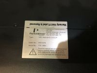
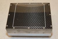
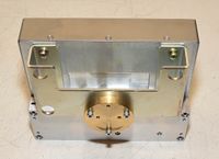
Perkin-elmer_xrd-1640_an19-ets-lp
"The MX-20 had an Perkin Elmer panel sensor with parallel output to an SCSI PC interface board. It can do medium sized boards, up to 10" x 12"...The P-E sensor that came with my MX-20 was not it's original sensor. My MX-20 was non-digital, just a film based one (or phosphor plate based). The P-E had a low voltage differential, parallel, output that was sent through a cable to a PCI frame capture board. The board (made by Perkin Elmer) looked like a SCSI interface to the PC. The sensors are available on eBay, sometimes for a good price, but I've not seen a complete system, sensor, power supply, cables, interface card, and software, in a long time. A sensor is on eBay now, see"
tvrsales2 https://www.ebay.com/itm/PERKIN-ELMER-DIGITAL-X-RAY-DETECTOR-SYSTEM-XRD-1640/233202476578
PERKIN ELMER DIGITAL X-RAY DETECTOR SYSTEM XRD-1640
McMaster
2020-02-24
tube in unit
tfx-8050

http://www.trufocus.com/xray_datasheets/microfocus/8000-SWS-Side%20Window/8050%20SWS/MFX-8050-SWS-V01.pdf
50 kV max
power supply
gamma high voltage
XR15-35P/M530A
https://www.ebay.com/itm/Gamma-High-Voltage-Research-rr125-2-5p-ttl-10v-m336-power-supply-w-tcm-1500/362920316155?hash=item547fbc8cfb:g:c9wAAOSwwD1eTcZE
hmm thats interesting
mcmaster@necropolis:~/doc/ext/gnome-tweaks/gtweak$ meson builddir
The Meson build system
Version: 0.45.1
Source dir: /home/mcmaster/doc/ext/gnome-tweaks/gtweak
Build dir: /home/mcmaster/doc/ext/gnome-tweaks/gtweak/builddir
Build type: native build

ERROR: First statement must be a call to project

A full log can be found at /home/mcmaster/doc/ext/gnome-tweaks/gtweak/builddir/meson-logs/meson-log.txt
faxitron summary
-Missing key
    Fix: jimmy lock
-Door switch broken
    Fix: tape screw to door
-X-ray not working?
    left light usually doens't go on, although right light always goes on
    geiger counter not detecting radiation
four0four:b8647895d5133f20d6b33c4a7b25d061
8:53
during operation I'm going like -2 mV
set to 35 kV, I should be getting like 35V

70 mV => low current as well?
if you hold start it has a count down timer
probably for warm up
with fuses removed right light comes on
but left light no longer does
fuses okay
LPQ252 main supply
is it okay?
LPQ252-C -  AC/DC Enclosed Power Supply (PSU), 4 Outputs, 250 W, 5 V, 35 A, 12 V, 10 A
big terminals
5V
can I get the tube or power supply out of the dx-50?
9:26
compare dx-50
power board: all three LEDs come on during fire
idle just one near the input power connector
10:24
flip top switch
time display changes from 010 to 0
in real time even if its on already
also can't hit start any more
remote still does nothing

bottom switch
no visible effect

default is rocked closer to the big IC near it
in special mode
pressing 9: L3 on kV
can up/down number
can go negative
only responds to up, down, and enter
11:00
DX-50
50 mV across hv ps variable resistor
white wire is required
gah need to re-test on mx-20
black power supply HV in
exceeded multimeter vmax
doesn't seem to have damaged it though?
doesn't kick in unless run command executed
10V across divider
+ is reversed vs the HV connections
ie brown at top is 0V
10 kV
    2.819V
20 kV
    5.68V
30 kV
    8.55V
35 kV
    9.88V
check VM (orange)
10 kV
    0.992V
20 kV
    2.001V
35 kV
    3.478V
power supply board behind it
measured while beam off
referenced to black box black wire
3x blue left fuse, 2x
    5.07V
3x orange middle fuse
    11.97V
1x brown right fuse
    -11.97V
big power supply
referenced to black box black ground
V1
    5.10V
COM
V4
    22.55V
RETURN
    -3mV
V3
    -11.97V
COM
    -0.7mV
COM
    -0.4mV
V2
    11.98V
small
    red 15.08V
    big 0
    red 4.97V
MX-20
referenced to black box black ground
V1
    5.03V
COM
V4
    24.55V
    TODO: verify other. Double checked this
RETURN
V3
    -12.01V
COM
COM
V2
    11.89V
small
    red 14.88V
    big
    red 4.92V
5, 12, -12V okay

Vm 0 under HV
Vref is 10V when set to 35kV, 2.834V when 10kV
next: can I check control signals into HV board?
powered off and unplugged
note this killed the fans
brown
    -11.99 V
white
    0.6 mV
green
    0.5 mV
orange
    11.91 V
black
    -300 mV
(space)
red
    0 V
    think this is a return line
this basically just goes to the big power section
if I had better probe access to that board might make debugging easier
Teledyne dalsa CD26M112 X1
Dalsa Teledyne Xineos CMOS Xray Detector 130mm X 130mm CD26M112 X1
Misc
Jul 31, 2018 Hologic acquired Faxitron Bioptics for $85,000,000
Tweets
- Trying to recover CD data: https://twitter.com/johndmcmaster/status/1214059627576360960?s=20
- On ham power supply: https://twitter.com/johndmcmaster/status/1214058462591631360?s=20
- DC5 vs DC12 cover off: https://twitter.com/johndmcmaster/status/1214056617336926208?s=20
- DC internals: https://twitter.com/johndmcmaster/status/1214055732741435392?s=20
